Serial Tx Rx Gnd
This is the configuration screen for PuTTY:Click Serial (1) then enter the COM port number (2) then click Open (3). Mac - using screenFind the serial port that is being used using the Terminal program command line: ls /dev/cu.usb.It should return something like /dev/cu.usbmodemFD1161.Then issue the command: screen /dev/cu.usbmodemFD1161Screen allows you you both send characters to the Photon or Electron as well as receive them from the USB serial device. Linux - using screenFind the serial port that is being used using the Terminal program command line: ls /dev/ttyACM.It should return something like /dev/ttyACM0.Then issue the command: screen /dev/ttyACM0Screen allows you you both send characters to the Photon or Electron as well as receive them from the USB serial device.
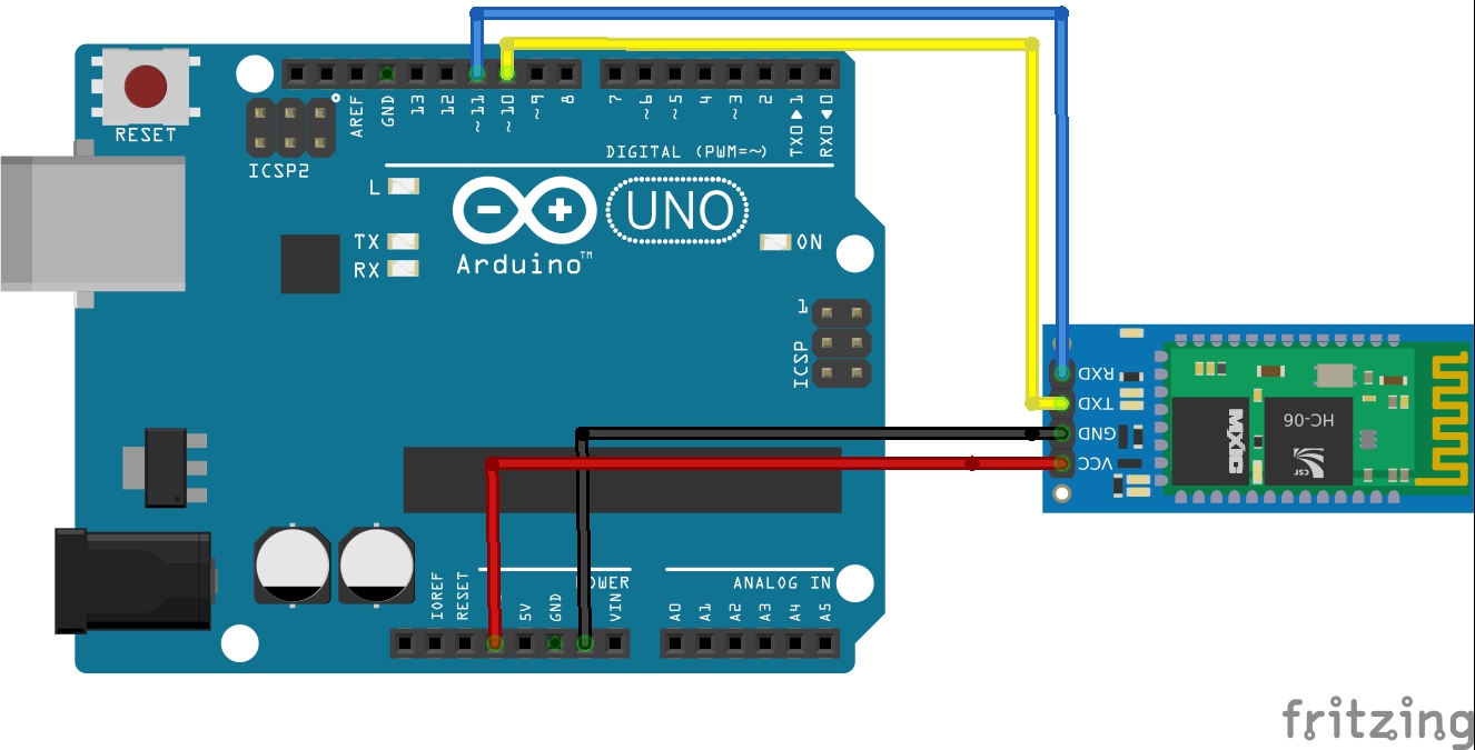
A common mixup with UART serial is that RX on one board connects to TX on the other! However, sometimes boards have RX labeled TX and vice versa. So, you'll want to start with RX connected to TX, but if that doesn't work, try the other way around! Connect GND on the Feather to GND on the GPS. Connect RX on the Feather to TX on. A serial bus consists of just two wires - one for sending data and another for receiving. As such, serial devices should have two serial pins: the receiver, RX, and the transmitter, TX.
Android phone or tablet with USB OTGIf your Android phone supports USB OTG (“on the go”) and you have an OTG adapter cable, you may be able to use it for debugging serial! One caveat is that your phone probably won’t power up a Photon, so this will probably only work if you have an external power source, like an Electron or Photon with a battery.Install the “Android USB Serial Monitor Lite” application from the Google Play store.Connect the device to your phone using a USB cable and a USB OTG adapter.Open the serial monitor app and it should ask if you want to connect to the device.
Tap yes and you should see a screen in the picture above. Configuration using USB SerialIf the Photon is in listening mode (blinking dark blue), configuration can also be done using the USB Serial port. Each of these commands only requires that you type the command letter (case-sensitive):. i - Prints the device ID (24 character hexadecimal string). f - Firmware update (using ymodem). x - Exit listening mode. s - Print systemmoduleinfo.
v - System firmware version. L - Safe listen mode (does not run user code concurrently with listening mode). w - Configure Wi-Fi.
m - Print MAC Address for the Wi-Fi adapterListening mode is the default when you plug in a Photon the first time. You can also get into listening mode by holding down SETUP for about 3 seconds until the status LED blinks blue.The commands other then the last two Wi-Fi related commands are also available on the Electron. Changing operating modes with USB SerialNormally you press buttons to enter listening or DFU mode on the Photon or Electron. You can also trigger it by making a USB Serial connection at a specific baud rate.For example, on the Mac you can use this command to enter DFU mode: stty -f /dev/cu.usbmodemFD1141 14400(The device name, cu.usbmodemFD1141 in this example, may be different on your computer.)The special baud rates are:. 14400 DFU mode (blinking yellow). 28800 Listening mode (blinking dark blue)UART SerialWhen connecting to an actual serial device, you’ll be using one of the UART hardware serial ports.
The Photon has one and the Electron has three UART serial ports.All of the devices have the Serial1 object, the main UART serial port, on the RX and TX pins. RX means serial data received into the device.
TX means serial data transmitted from the deviceWhen you connect a Photon another device, say an Arduino, the RX pin on the Photon always gets connected to the TX pin of the Arduino and vice versa. This is always the case, even if you connect two Photons by serial.The Photon actually has two and the Electron four UART serial ports. The catch is that Serial2 is on the same pins as the RGB status LED.
Using it requires soldering and disabling the status LED, which will make troubleshooting your device very difficult. It’s a complicated enough topic that it. Additional ports on the ElectronThe Electron has two additional UART serial ports that you can use,. C0 Serial5 RX. C1 Serial5 TX. C2 Serial4 RX. C3 Serial4 TXIf you need Serial4 or Serial5 you’ll need to enable the port by adding one or both of these includes near the top of your main source file: #include 'Serial4/Serial4.h'#include 'Serial5/Serial5.h'Serial logic levelsThe Photon and Electron are 3.3V serial devices that are 5V tolerant.
When transmitting data, logic 1 values are 3.3V and logic 0 values are 0V, so we list the port as being 3.3V.Many 5V serial devices will correctly respond to 3.3V values as logic 1 even though it is out-of-spec. Likewise, the Photon doesn’t mind having 5V levels for logic 1 on the RX pins.
So you often can connect a Photon directly to a 5V serial device, like an Arduino. This is often referred to as “TTL serial” as it uses the 5V logic levels used by TTL (transistor-transistor logic) devices.One thing that you absolutely must never do is connect a Photon directly to a computer or other device using an actual RS232 interface.
A converter is required and is described in the next section. Interfacing to RS232 devicesActual RS232 devices, such as old computers, newer computers with an adapter, and various external hardware devices likely use “real” RS232 signal levels, which can range between +15V and -15V. This will cause immediate, permanent damage to the Photon or Electron if connected directly.A TTL serial to RS232 adapter board is typically used in these cases. They are available from places like SparkFun.
You can also find them on eBay, search for “TTL RS232 breakout”. Make the following connections:. Converter VCC to Photon 3V3 (red). Converter GND to Photon GND (black). Converter TX-O to Photon TX (green).
Converter TX-I to Photon RX (blue)Note that TX and RX don’t cross here, between the Photon and the converter, because they’re crossed in the RS232 serial cable DCE to DTE connection. ConnectorsTwo different connectors are used for RS232 serial, the DB9 and the DB25. The DB25, a “D” shaped 25-pin connector was the original connector but IBM PC compatible computers mostly settled on the smaller DB9 connector. The DB9 is also referred to as a DE9 connector.This is a close-up of the DB9 female connector on the SparkFun converter board. DTE/DCESerial devices are either DTE (data terminal equipment) or DCE (data communication equipment).
These names come from the early days of dumb terminals (DTE) connected to modems (DCE). It doesn’t entirely matter which device is which, but if you have to connect two like items (say DTE to DTE) you need a null modem adapter that crosses the TX and RX lines (among others).Typically DTE devices have a male connector. Pin 2 is an input and pin 3 is an output.Likewise, DCE devices typically have a female connector. Pin 2 is an output and pin 3 is an input.The Sparkfun board has a female DB9 and makes the Photon a DCE. This makes sense because most computer serial ports are DTE. Baud rate, bits, parity, and stop bitsThere are four configuration parameters for serial, and you must make sure they’re all set correctly, otherwise communication will often fail, either with no data or garbage characters received.The baud rate is the speed that data is sent.
A common value is 9600. The valid values for the Photon and Electron are 1200, 2400, 4800, 9600, 14400, 19200, 28800, 38400, 57600, and 115200. Neither device can use speeds under 1200 (such as 300 or 600).The number of bits per byte is typically 8. It’s occasionally 7 or 9.
The easy way: using DriverMax to install FILMSCAN 35mm Film Scanner driverThe advantage of using DriverMax is that it will install the driver for you in the easiest possible way and it will keep each driver up to date, not just this one. How easy can you install a driver with DriverMax?  If your UAC (User Access Control) is running then you will have to confirm the installation of the driver and run the setup with administrative rights. Let's follow a few steps!. Follow the driver setup wizard, which should be pretty easy to follow.
There is limited support for 9 bit in system firmware 0.5.0 and later, and full support for 7 and 9 bit in 0.6.0 and later.The parity is a method of detecting errors in the data. It can be none (“N”), odd (“O”) or even (“E”). Support for parity is included in 0.5.0 and later.The number of stop bits is 1 or 2.
Support for stop bit setting is included in 0.5.0 and later.The last three things are typically combined into a single string, for example “8N1” means 8 bits, no parity, 1 stop bit. “7E1” means 7 bits, even parity, 1 stop bit. And so on.The available values are:. SERIAL7E1. SERIAL7E2. SERIAL7O1.
SERIAL7O2. SERIAL8N1. SERIAL8N2. SERIAL8E1. SERIAL8E2. SERIAL8O1.
SERIAL8O2. SERIAL9N1. SERIAL9N2You use these with the call, for example: Serial1.begin(9600, SERIAL9N1);Flow controlThere are two types of flow control in serial: hardware (RTS/CTS) and software (XON/XOFF).The Photon does not support hardware flow control (RTS/CTS). The Electron does not currently support hardware flow control.Neither the Photon or Electron support software (XON/XOFF) flow control, either. In some limited cases, you could note when you receive XOFF (Ctrl-S) in your received data and stop sending, however there is currently no way to stop the send FIFO from sending, so this will only work when you don’t have any data waiting to be sent.
Communicating with an ArduinoHere’s an example of using serial to communicate between an Arduino (Uno, in this case) and a Photon. Photon TX connects to Arduino RX (0) (green wire). Photon RX connects to Arduino RX (1) (blue wire). Photon GND connects to Arduino GND (black wire)Remember: RX and TX always cross, and you must have a common GND connection.This is a rather silly example: Every 2 seconds the Photon sends a number to the Arduino by UART serial. The Arduino parses this number, increments it, and sends it back.

The Photon prints it out via the debugging serial.Remember that serial is a byte-oriented protocol, so we keep reading bytes until we find a character that marks the end of the transmission. I selected the new line character ('n'). Great tutorial, but I’m finding one thing missing. I’m trying to push relatively high bandwidth data over the USB serial channel to a photon.
I’m asking for a baud rate of 115200 in my Python code on the PC and in the serial.Begin(115200) on the photon. I believe the photon one will definitely be ignored, but it also appears that regardless of what baud rate I set in my Python code, the photon only ever talks at 9600 baud over that serial link. Is there a method by which I can set a higher baud rate on the photon’s USB Serial and actually have that setting actioned? Rickkas7:The Serial.begin(9600); call initializes the serial port. When you’re using the USB serial, t.he value doesn’t actually matter. Sometimes you’ll see Serial.begin(115200); but it really runs at the same fast speed regardless.For that reason USB Serial even supports a parameterless overload Serial.begin that should make it absolutely clear that baudrate is irrelevant on the device side.And from the host side, the set baudrate should also not impact the transfer speed as USB reports are usually sent with the default USB 2.0 speed (unless your drivers “interfere”). ScruffR:How did you “measure” this?Hey Scruff,I wrote a python script using pySerial that blatted data at the photon in packet sizes of 1, 10 or 50 bytes, then timed how long it took me to spit a couple of K down the link at each of those packet sizes.
The serial port was opened at 115200 baud, and I think I was testing using a total transmit of 2050 bytes. The photon had a callback firing on each RXd byte using the SerialEvent callback, but wasn’t actually doing anything with the data. When I did deeper testing I was going to go in and look at inter-callback times and dropped bytes as the photon saw them.I was getting about 1K bytes/second over the link regardless of packet size. That led me to believe that:. Since the packet size seemed to be irrelevant it looked like a throttling issue with the link itself rather than my Python code. That number was was near enough to a 9600 baud asynch serial link that I figured there was something somewhere that was using that as a value.Since I don’t have RX and TX lines to stick my silly-scope onto that was about the most detailed testing I could come up with.
DKWEngineering:using the SerialEvent callbackThese are no real event callbacks but merely synchronous functions that are called between iterations of loop. This in combination with the misleading naming is an Arduino legacy which has caused some confusion with others before.Since loop gets called about every 1ms when cloud connected and you only reading one byte at a time, that might explain the 1K you got, but that’s not the max speed data gets transmitted.To do some “more precise” testing, you can disable the could connection and run a tight loop that permanently reads and counts bytes received over a given time. Serial(port=‘COM3’, baudrate=115200, bytesize=8, parity=‘N’, stopbits=1, timeout=None, xonxoff=False, rtscts=False, dsrdtr=False)That’s what Python’s giving me - All looks good. I just did a couple of minimal tests, and I have to admit I’m now more suspicious of Python than I am of the Photon. I think the next step will be to dust off a usb-3V3uart converter and try the same tests against the photon’s Serial1 at 115200 so I can get a scope on the TX and RX lines and get a better sense for exactly what’s going on.